Vehicles
In this first version of the Pegasus Simulator we only provide the implementation for a generic Multirotor Vehicles
and a 3D asset for the 3DR Iris quadrotor . Please check the Roadmap section for future plans regarding new vehicles
topologies and the Contributing section to contribute if you have a new vehicle model that you would like to be added.
To create a Multirotor object from scratch, consider the following example code:
from pegasus.simulator.params import ROBOTS

from pegasus.simulator.logic.dynamics import LinearDrag
from pegasus.simulator.logic.thrusters import QuadraticThrustCurve
from pegasus.simulator.logic.sensors import Barometer, IMU, Magnetometer, GPS
from pegasus.simulator.logic.vehicles.multirotor import Multirotor, MultirotorConfig

# Auxiliary scipy import to set the rotation of the vehicle in quaternion
from scipy.spatial.transform import Rotation

# Create a multirotor configuration object
multirotor_config = MultirotorConfig()
multirotor_config.stage_prefix="quadrotor"
multirotor_config.usd_file = ""

# The default thrust curve for a quadrotor and dynamics relating to drag
multirotor_config.thrust_curve = QuadraticThrustCurve()
multirotor_config.drag = LinearDrag([0.50, 0.30, 0.0])

# Set the sensors for a quadrotor
# For each sensor we are using the default parameters, but you can also pass in a dictionary
# to configure them. Check the Sensors API documentation for more information.
multirotor_config.sensors = [Barometer(), IMU(), Magnetometer(), GPS()]

# The backends for actually sending commands to the vehicle.
# By default use mavlink (with default mavlink configurations).
# It can also be your own custom Control Backend implementation!
#
# Note: you can have multiple backends (this is usefull for creating backends
# for logging purposes) but only the first backend in the list will be used
# to send commands to the vehicles. The others will just be used to receive the
# current state of the vehicle and the data produced by the sensors
multirotor_config.backends = [PX4MavlinkBackend()]

# Create and spawn the multirotor object in the scene
Multirotor(
        stage_prefix="/World/quadrotor",
        # The path to the multirotor USD file
        usd_file=ROBOTS['Iris'],
        vehicle_id=0,
        init_pos=[0.0, 0.0, 0.07],
        init_orientation=Rotation.from_euler("XYZ", [0.0, 0.0, 0.0], degrees=True).as_quat(),
        config=config_multirotor,
    )
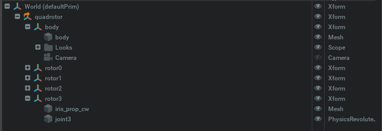
To define and use a custom multirotor frame, you must adhere to the adopted convention. Therefore, a vehicle
must be made in a USD file and have a /body and multiple /rotor<id> Xform objects. Each rotor /rotor<id>
must have inside a Revolut Joint named /rotor<id> where the <id> of the joint must coincide with the Xform name.
An example tree of the 3DR Iris quadrotor is presented bellow.
Additionally, you should set the mass and moments of inertial of the materials the compose the vehicle directly in the USD file, as well as the physics colliders.